Tuesday, October 20, 2015

Using GEM's Software to construct geotiff's and checking GEM data


Introduction:

GEMs stands for Geo-localization and Mosaicing System.  This software is used to visualize the flight data gathered from the GEMS hardware payload. GEMs is a custom built sensor UAS applications on small UAVs. The software will automatically access the sub-images recorded to the storage media (jump drive) from the flight and the corresponding metadata.  Orthomosaiced RGB (red, blue, green), NIR or NDVI (Normalized Difference Vegetation Index). 
Hardware: 

Gem is a precision agriculture multispectral sensor payload for remote sensing on small UAV's.  It is designed to be a completely stand alone hardware sub system.  This design allows for ease of integration on any size and type of platform such as a fixed wing, rotary, or RC.  The GEMs hardware captures RGB, NIR, and DNVI imagery in a single flight. 
The Ground Sampling Distance (GSD) is 5.1cm @ 400 feet and 2.5 cm @ 200 feet.  The height and the speed of the plane is very important in regards to image quality.  The higher the altitude and faster the plane flies, the lower the quality of the image will be.  If you fly the plane lower and slower the image quality is better image quality.

GEMs stores the data on a SanDisk Extreme 32GB jump drive media storage device is provided with the GEMs payload.  You can use an upgraded one also of 64GB but it is not recommended to use another disk other than the SanDisk for this product.  When mounting the GEMs on the UAS always make sure it is pointing towards the ground.  No magnetic material should be placed within 4 inches from the payload itself.  Magnets will result in an iron anomaly in the magnetometer data and will show up on the mosaicked imagery as misalignments.   Vibrations should be minimized by placing a piece of foam between the payload and the motor for insulation.


Parameters for Flight Planning Software:  The GEMs payload uses low-distortion optics and for the purpose of flight planning any distortion (radial and tangential) can be assumed negligible.  The appropriate value for overlap need to be set starting at 70%.  The system will gather images automatically at a rate of 0.7-0.9 seconds between images. 

Figure 2: This image is the Parameters for Flight Planning Software.   


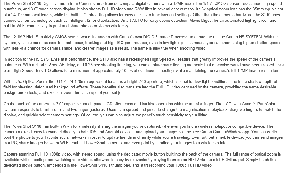
Cannon S110:
Figure 4:  Additional Resolution Information for movies and
compression. 


Figure 3:  Still image Resolution of the Cannon S110.


The Cannon SX260:


Figure 5:  The Cannon SX260 has the same operating system requirements as the GEMs software and Adobe Reader is required for installation. 


Figure 6:  This information is shots per memory card and that the pixel data for large, medium and small images. 


DJI Phantom Sensor:
Figure 8:  List of basic features of the advantages of the DJI Phantom Sensor. 

Go Pro: Hero


Figure 9:  Resolution information for the Hero from Go Pro. 


Software Manual:

Currently, GEMs software is only compatible with Windows operating systems (Windows7 and Windows 8). 
Every flight is automatically labels a new folder with the Flight Data, ex.  (Week=X  TOW=H-M-S). 
These they are set as numbers immediately when the data collection begins. 

The difference between orthorectified and georeferenced is very important. 
Georeferenced means to associated something with locations in physical space.  The term commonly used in the geographic information systems field to describe the process of associating a physical map or raster image of a map with spatial locations.  (Hill, Linda L. (2006). Georeferencing. The MIT Press. ISBN 978-0262083546.  An orthophoto is an aerial photo geometricaly corrected or orthrectified such that the scale is uniform:  the photo has the same lack o distortion as a map.  It can be used to measure true distances, because it is an accurate representation of the Earth's surface, having been adjusted for topographic relief, lens distortion and camera tilt.  Orthorphotos are commonly used in the creation of Geographic Information System (GIS). 
Smith, Gary S. "DIGITAL ORTHOPHOTOGRAPHY AND GIS." ESRI Conference. http://proceedings.esri.com/library/userconf/proc95/to150/p124.html


Figure 10:  This figure shows the orthographic image and how it differs from perspective view. 


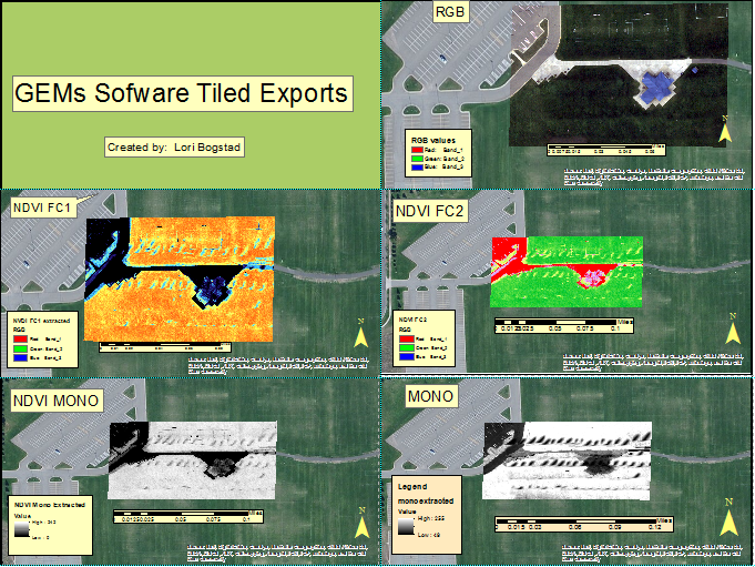
Below the maps show 5 different types of images. 

Figure 11:  This shows the different types of images that can be taken with the GEMS software.  The RGB, NDVI FC1, NDVI FC2, NDVI MONO and MONO. 

RGB: Color model that defines colors in terms of relative amounts of red, green and blue components; black is defined as zero amount of the components, white is the maximum of the components. 

NDVI:  Normalized Difference Vegetation Index is a simple graphical indicator that can be used in remote sensing measurements, typically but not necessarily from a space platform, and assess whether the target being observed contains live green vegetation or not.  The FC1 colors are not representative of a what would be considered such normal expected color scheme.  The FC2 shows vegetation in green which is what we would expect to see in a normal photo. More pleasing to look at. 

REVIEW OF GEMs:
 
I feel that the GEMs system is very innovative.  I actually thought the manual for the Hardware was very informative and had a lot of information that made it easy to understand.  Other parts were in so technical that I had to read them numerous times and look up some terms to somewhat understand it.  I felt there should be more definitions of terms and more practical aspects instead of all the technical terms that only someone in the field could answer.  The Software manual was confusing and it appeared to repeat the same thing in numerous areas but not answer vital questions such as what a lot of the terms meant and how they worked together.  The fact that it claims that the images are orthorectified  is not accurate as well.  I found it to be a lot of information about the different photo types but they were not well organized for ease of understanding.

I felt overall the manual was better than all of the other manuals I looked up online.  The Cannon S110 was the only manual to compare.  The rest of the manuals were very minimal.  I would chose to use this software even though it is a bit confusing.  I feel that if I spent more time reading the software manual again I would further understand it. 


Tuesday, October 6, 2015

Conducting Operations with Multi-Rotor UAS


Introduction:

The day was Wednesday, September 23, 2015.  This field exercise was intended for us to learn how to use the flight plan software and conduct a mission.  Then we put the flight plan in the computer to watch the aircraft complete the flight plan.  We also learned a great deal of information on batteries and how and when to use them.  We did have some technical difficulty with the fixed wing so we only flew the Matrix.  Each group did the preflight checklist and checked the flight as it was in progress and gave information to the pilot. I will go through all these items I great detail in the Methods portion of this assignment. 

Study Area:

The Eau Claire Indoor Sports Center is located at 3456 Craig Rd, Eau Claire, WI 54701.  We performed the flight plan at this location in the northern part of the parking lot.  The weather this day was partly cloudy with many cumulostratus clouds present. 
79 degrees F
Wind SE 10mph
Humidity 51%
Dew Point 60 degrees F
Pressure 30.18

The forecast says it should rain in 99 minutes and it is presently 4:22 p.m.  The forecast also calls for thunderstorms ESE at 7 mph.  We decided at the last minute to try to make this work after the forecast changed from saying it would rain all day. 

Figure 1:  Indoor Sports Center located in Eau Claire, we used the open soccer fields to fly our missions.  The area highlighted in yellow is the area we used in our flight plan. 


Figure 2: Location of the Eau Claire Indoor Sports Center and the adjacent Soccer fields used for flight. 

 
Methods:

We divided into groups and using the Flight Plan software each group use the computer to do the preflight check list and checked all the information listed on the Excel sheet to make sure that the flight would be successful.  One person manned the computer which is the pac and the other ones took the Matrix to the take off area.  The person with the transmitter is called the pic. Then the whole entire checklist is read off and completed making sure that the plane is ready for take off with no problems with the aircraft.  Then right before flight you need to check the area for anything that may interfere with your flight, such as others flying, kites, people walking, playgrounds, any activity that may be bothered by the UAV or may disrupt the mission.  Once the area is clear and you are ready for take off, move away from the aircraft and start the mission.  The group then watches the screen on the Flight Plan software to make sure that the aircraft is flying correctly.  You need to keep communication with the pilot to let them know if there is any trouble or even if things are going smoothly.  When the aircraft is close to the end of the mission, the pilot is informed that it is coming home.  You then do the same type of check for surroundings before landing to make sure surrounding have not changed within the flight plan time.  Once the aircraft is landed, again check the plane for any damages or any lose parts.

Figure 3:  Students preparing the flight plan and doing the re-flight checklist.


Figure 4:  Michael Bomber tightening a few screws in the pre-flight to ensure the aircraft is ready for take off. 


Figure 5:  Dr. Hupy preparing the camera for the flight. 

 
The camera was directly hooked on the platform on the Matrix, it was attached by a customer platform.  The camera was set to take pics at a certain interval and then the aircraft has to be checked for stability that it is not too heavy in the front in order for it to take off properly. 

During the time when one group was doing their flight plan, Dr. Pierson gave us an informational talk about batteries.  He explained the differences in the batteries and how they are to be used and many problems that can occur.  First the battery will have a label on it such as 1s,  2s, 3s or 4s.  The batteries were are using are lithium polymer. A one cell battery (1s) has 3.7 volts.
How much energy they store is called miliamps (mAh) which indicates hours of use.  The C- rating is how much current is produced.  Charge rate- max current to charge it. You should never let your battery charge get too low, if you do you could ruin the battery.  Also always inspect your battery, if it has rips, tears or bulges don't use it, its not worth crashing. When needing to charge your battery it will take about 30-40 minutes and over an hour on bigger ones. Never put water on a lithium battery fire, always use sand.  This day we used a G5 battery for flight. 


Figure 6:  Dr. P showed us a large amount of batteries and explained the differences and how they are used.  He showed us how to check the batteries as well.  This image also has some different examples of propellers. 

Some other helpful information is dealing with the propellers.  The prop # needs to be facing out at all times.  Never use props that are damaged or cracked.  They are very inexpensive and not worth crashing over.  The higher the pitch number the more it goes and needs powerful engine and more battery to fly. 

Since we had some time left over, Doc P showed us the plane he made and went over some changes he made to it to make it fly better.


Figure 7:  Doc P explaining some of the aspects of the aircraft that we are building.

Figure 8:  Doc P and his finished plane that the class will also build. 
Figure 9:  Fixed wing that had trouble flying but still interesting to look at an examine. 
Discussion:

The outcome of this field day was a completed mission with the Fight Plan software.  We did not do as many flights as we intended as it was getting a bit rainy.  The methods did work in this instance.  We were not able to fly the fixed wing due to difficulties with it.  The Matrix did fly the pattern indicated and there were a few people that came in to the soccer fields for practice and we watched for them carefully.  This is another reason we did not conduct another mission.  During the landing there was a woman who almost started walking towards it. This is why you would want to conduct a mission that is not near so many people but this worked for our purposes. 

Conclusion:

This day we set out to learn how to do the preflight check list in a real situation.  We did succeed in our mission.  We learned that surroundings can change while in flight so always be aware of them.  We learned a lot about the batteries and how they work and what they work for.  The multi-rotor mission planning software was easy to use and the mission was complete and we had a safe landing.  This exercise showed us how to run a mission in a real life situation as opposed to only doing the checklist and not flying as in the previous exercise.  This is just one step in learning more about this technology and learning how to efficiently use it. 


Monday, October 5, 2015

Using a multi-rotor to gather imagery and using mission planning software

Introduction:

At the beginning of class we learned some information on the flight plan software to prepare of for our field activity outside in the commons area.  We went outside to learn how to do the pre-flight check list and to learn how it looked on the computer.  We then learned how to check the items on the pre-flight check list on the Matrix.  We moved around stations and learned to do each station. We did set up a flight plan but did not fly the Matrix this day. After observing the cloud cover, it was mainly overcast but there were scattered alto cumulostratus clouds.  The temperature was 81.1 degrees F and there was a 3 mph wind S SE direction.  This day prepared us for real time when we are doing the checklist for real and checking all the parts of the aircraft to ensure it flies safely. 


Figure 1:  Computer used to do the preflight check list.

Study Area:

Figure 2: Study area between Davies Hall and Phillips Hall at the UWEC campus. 
 
We went outside in the commons area between the buildings and used the tables to do the computer part of the check list.  We all gathered around the tables to learn how to do the checklist and then used the courtyard in the yellow area to do our mock preflight checklist. 

Methods:

First we sat down at the tables and split into groups.  Each group had a chance to sit at the computer and read the checklist to our team mates who were at the aircraft performing the checklist from there. 
The checklist had a large list of items to go down the list.  The computer person yells out to the team member with the aircraft:
electrical connections ?
frame connections?
motor connections?
prop secure and no cracks?
battery secure?
battery balanced?

The team member with the aircraft then answers these questions back with repeating the question back.  Such as the person doing the check list with the aircraft would say for example, "prop secure, no cracks," and so on for each item. 

The TX is the transmitter and the RX is the receiver. 
We then checked to see if the modem is connected, Pac Person on computer and then we did the mission software.  We used com 5 57-600 frequency.

There were 11 satellites at the present time, you should not try to use your aircraft with less than 6 satellites. 
 The yaw (degrees) oriented North

G3 battery at 8 volts
We did the whole process just like we were flying that day.  Each group was able to do each activity. 


Figure 3: Michael Bomber showing Cullen and Ethan how to the parts of the checklist that involved the aircraft. 
FIgure 4:  Station where the flight plan is checked and Michael was checking the wind for the weather portion of the checklist. 

 
 Discussion:

 This exercise of a mock flight was very informative. I learned a lot from it.  The pre-flight checklist is a lot more extensive than I thought, there were many items on it I would not have thought of.  All the items on the check list are very important.  I do think I could perform the checklist by myself so I feel comfortable with that. I do think I could learn how to use the flight plan software a little better.  This hands on approach helped me understand many different aspects of the task.

Conclusion:

The activity taught me a lot.  There are so many different aspects of flying a plane.  There are many different aspects of planning a flight, including weather, surroundings, safety and the aircraft working properly.  There also needs to be enough satellites to use to make the flight plan successful and to have the plane return home.  There a so many things to do but once you learn them, you learn to fly safely for anyone around you and the safety of the aircraft as well.


Wednesday, September 16, 2015

Image Gathering Fundamentals

Introduction:

This activity was designed to learn and understand how to gather imagery by putting a camera sensor on an aerial platform and taking images that can be used later for geospatial analysis.  The idea is to take many pictures of the area and use all the pictures to make an image to understand the study area better.  This exercise is designed to teach us how to set up a Picavet rig and how to use the cameras appropriately to achieve the desired results.  Located below are some pictures I took in preparation for flight. 
Figure 1:  Class holding the kite and waiting to prepare it for flight. 
 
Figure 2:  Dr. Hupy attaching the cameras to the Picavet rig. 
 

Figure 3:  Kite ready for departure with cameras attached.


Figure 4: Very calm day with little wind, 67 degrees F.  This was a perfect day to fly the kite.   

Study Area: 

The study area was the soccer field right next to the Indoor Sports Complex parking lot.  It is located at 3456 Craig Road in Eau Claire, WI.  The study area was quite large and it was the length of the fields combined.  The wind was very mild this day, there was little movement to speak of.  There were a few rain drops here and there but nothing that caused any difference in the results of what we were trying to achieve.  We did end a little early due to rain on the cameras.  The temperature was 67 degrees F.  This was a good day for the balloon and taking pictures.  Too much wind would have made it difficult. 


Figure 5:  The image above indicates the study area location.  It was on the east side of the Indoor Sports Complex.  The area is outlined in green. 

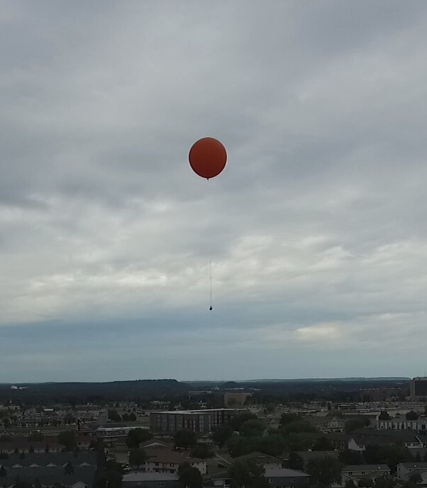
Figure 6:  One of the pictures that shows the kite flying and a gorgeous sky

.


Methods:

First the needed to attach the kite to the Picavet rig.  There are several variants on the way to lace the Picavet system.  We attached the cameras to the rig and one of the cameras was altered to be infrared.  The Canon  Hacker's Development Kit, also known as CHDK is a unique software application developed by enthusiasts that enables extra features for ported Canon Point and Shoot cameras.  CHDK can offer features like RAW shooting mode, live RGB histograms, motion-detection, time-lapse, and even games on your existing camera. CHDK is non-permanent and non-destructive and makes no changes to your camera, and turning it off is simply a matter of restarting your camera.  It's simple and powerful, it is somewhat like hacking your router firmware but even easier.  Using this technology can be very important when needing to alter the state of some pictures or taking more pictures and extends recording time as well.  You can customize your on screen display which can include remaining battery life, depth of focus and histograms.  It takes the options already available on your camera and gives you way more options including faster shutter speeds, and longer exposure times.  This can be very helpful when a camera is so high up and you would like either more pictures or better quality pictures in a short period of time without using more battery life.
After Dr. Hupy explained the camera installation he decided to have the camera take pictures every 5 seconds.  We lifted the kite into the air and began our journey up and down the field.   As we walked down the field, when we got to the end of the zone in which we were covering we took 10 paces or 30 meters to the left and then began our journey back down the field.  I think that using paces may not have been our best options as some people have bigger paces, not sure if it really made a difference or not but at the end of the trip around the field I noticed that the "30" meters looked much more like 20.  So in order to do this more accurately perhaps a meter stick or a tape measure would have been more accurate. Just as we were finishing up, it began to rain.  We got the survey done without any issues.  We got the kite down in time in order for the cameras to not get wet.  We pulled the kite in and disassembled the rig and stopped the cameras from taking pictures.  I actually walked the whole entire length of the experiment.  It was exhausting but the images obtained were pretty amazing. 

Brooxes Picavet Lacing
Figure 7:  Brooks design of the +lacing. The variant only has 1 ring. 
   

H-Picavet
Figure 8:  Note that there are two rings used. 
     

Figure 9:  This is one of the pictures I took off the class folder, I cropped it a little to fit the page. Great view of the kite and the Picavet rig attached below. 

Discussion:

This outcome of this activity is to give us an idea how to use the equipment properly and to analyze the given situation to see if the results will be what we are looking for.  The fact that it was not windy this day will probably lead to better pictures and better overall consistent overlap so we can get a good image.  I believe the method of taking 10 paces was not as accurate as it could have been as some people were taller and took bigger steps and the fact that at the end it seemed that people were so eager to get it done due to the sprinkling of rain that they maybe took less steps than they should have.  We felt that there was a few times that maybe the paces were about 20 m instead of 30 m.  The pictures indicate that the area was well represented.