This is an overview of Pix4D Software. Pix4D is an image processing software that is a complete mapping and modeling solution to convert thousands of images into georeferenced 2D mosaics and 3D models.
Designing the Images Acquisition Plan:
In order to get accurate results, a high overlap between the images is required. A plan should be devised in order to have enough images and enough overlap. The amount of overlap depends on the project specifications and or terrain type. The Pix4D mapper is an image processing software that is based on automatically finding thousands of common points between images. Each characteristic point found in an image is called a keypoint. When 2 keypoints on 2 different images are found to be the same they are matched keypoints. Each group of matched keypoints will generate one 3D point. When there is high overlap between 2 images, the common area captured is larger andmore keypoints can be matched together. The more keypoints there are, the more accurately 3D points can be computed. For this reason, it is a good rule to maintain a high overlap between images. In general it is recommended to have an overlap of at least 75% frontal overlap and at least 60% side overlap.
For more difficult terrain such as snow, sand and lakes, use a high overlap of at least 85% frontal and at least 70% side overlap. You would also want to set as much contrast as possible in each image. It is impossible to reconstruct oceans, to reconstruct rivers or lakes, your image must contain a land feature. To do this you may need to fly higher to include more land.
The software also allows users to use Rapid Check processing. It can be used as to evaluate how good a data set is. If it doesn't show good results then this will show that the dataset is not adequate and it is necessary to get new images.
Pix4D can also process images taken from multiple flights. To do this make sure that each plan captures the images with enough overlap, there is enough overlap between 2 images acquisition plans and the different plans are taken as much as possible under the same conditions.
 |
| Figure 1: This demonstrates the recommended images acquisition plan for 2 flights. |
Ground Sampling Distance (GSD) defines the accuracy and the quality of the final results as well as the detail that are visible in the final orthomosaic. The flight height H to obtain a given GSD depends on the camera focal length, camera senor width (mm) and the image width (pixels).
Pix4D is ale to process images taken from any camera and can use perspective lens, or fisheye. The cameras can be loaded on any platform such as UAV hobby, professional UAV's Manned aircrafts, helicopters, terrestrial vehicles and even no platform, images taken by hand. It can can also process any images regardless of the spectral specifications of the camera, such as RGB, NIR cameras, IR cameras and thermal cameras.
Georeferencing is optional but recommended. When processing images with no geolocation, if no Ground Control Points are used, the final results have no scale, orientation and absolute position information. Because of this cannot be used for measurements, overlay and comparison with previous result. This may also produce an inverted 3D model in the rayCloud.
Methods:
Creating a New Project
1. Open Pix4D
2. Start New Project on the Main Page
3. Create Project Name and save it in an appropriate folder by clicking “Browse”
4. Click “next”
5. Select Images Window – click “add images”
6. Navigate to the images needed for the project. In our case the multirotor images SX260 RGB files. Select all photos.
7. Click “next”
8. Image Property Window – images already have coordinate information
 |
| Figure 2: Image Properties in New Project |
9. Confirm that the selected camera model is correct.
10. Click “next”
11. Processing Options Template Window – Select 3D Maps
12. Click “next”
13. Select Output Coordinate System Window – make sure auto detected is selected
14. Click “Finish”
 |
| Figure 3: Processing Screen |
 |
| Figure 4: Importing Gems |
 |
| Figure 6: Importing Gems further in process with Ray Clouds |
Processing:
1. Click “Start” on the bottom window to begin processing. This may take a while to complete.
- This will also generate a Quality Report


 |
| Figure 7: Processing |


 |
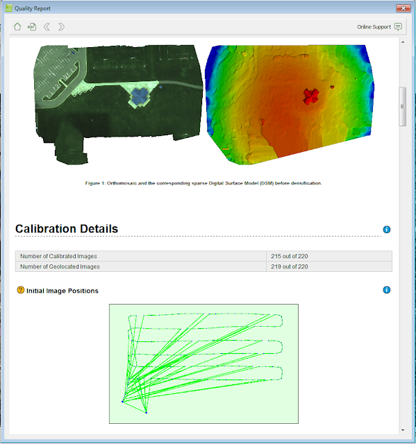
| Figure 8: Quality Report |
2. Review Quality Report when processing is finished. (There are specific things Dr. Hupy wants you to look up in the report – make sure to include them/discuss them in your blog).
Below is how to analyze a Quality Report:
1. Quality Check, verify that:
- All the checks are green
- All or almost all the images are calibrated in one block
- The relative difference between initial and optimized internal camera parameters is below 5%.
 |
| Figure 9: Quality Check |
For projects the images are nadir and for which the orthomosaic has been generated, verify that the orthomosaic does not contain holes or does not have distortions. If GCP's or geolocation has been used, that it has the correct orientation.
3. Initial Image Positions
4. Computed Image/GCP's Manual Tie Points Positions, verify if using images with geolocation, that the geolocation images are good. If using GCP's, that the GCP's error is low.
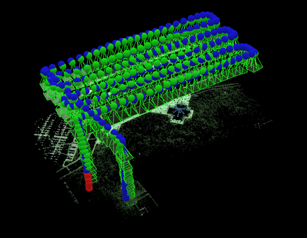
5. 3D Points from 2D keypoint matches, verify that enough matches have been computed between images and the graph consists of one block
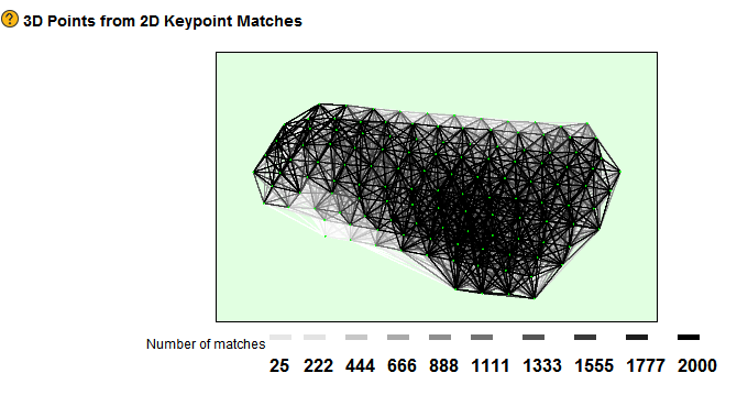 |
| Figure 10: Keypoint Matches |
6. Geolocation Details, if using GCP's, verify that all GCP's are taken into account (not displayed with red color on the Geolocation and Ground Control Point table. That all marked GCP's have been verified. Lastly, check to see if the green circle representing the reprojected GCP 3D point is inside the yellow circle representing the marked GCP.
 |
| Figure 11: Ground Control Points (GCP's) |
3. Deselect “cameras” in the Ray Cloud Tab
4. Select “Triangle meshes” for a better image of your area
 |
| Figure 12: Final Processed in Pix4D |
Calculate Area of Surface:
1. Right click “objects” in left window and select “New Surface”
2. To begin a new surface left click a desired area to add a vertices.
3. Continue to left click until you have nearly completed covering your new surface
4. To finish right click to close the surface.
5. Right click your new surface in the left window and rename it appropriately
6. Then click on the new name to view the measurements in the right window.
 |
| Figure 13: Area of a surface |
 |
| Figure 14: Distance of a surface |
 |
| Figure 15: Distance of a surface |
**Same instructions for the calculate distance accept you select “New Polyline”**
***Same for Volume except there is an extra step at the end***
7. Click “update measurements” in Right window to view calculated measurements
Creating Animation Trajectory:
1. Right click “objects” in left window and select “New Video Trajectory…”
2. Click “next” in the video animation trajectory Wizard
3. Create WayPoints – set desired position and then click “Record Trajectory Waypoint” Repeat this process until you are satisfied with trajectory path and orientation.
4. Click “next”
5. Set up Desired Duration and speed
6. Click “Finish”
 |
| Figure 16: Trajectory Animation photo |
 |
| Figure 17: Use of way point to make animation and status. |
7. Click play in side window to visualize animation.
8. Click Render
9. Finally, save animation in desired folder
Figure 18: Animation of trajectory.
Part 3: Making Maps
Open ArcCatalog
Create a database name accordingly
Import data sets generated by the Pix4D software into the folder
Use ArcMap to create the series of maps with the images collected and using all the shapefiles created for the line, volume and surface area.
First map created is the using the Pix4D and I brought it in the ArcMap and added the features and shapefiles to create the map.
 |
| Figure 19: Gems Soccer Park with all shapefiles added from ArcMap. |
 |
| Figure 20: Volume of an outbuilding |
 |
| Figure 21: Polyline Vertices for distance |
 |
| Figure 22: Sidewalk Surface
|


 |
| Figure 23: SX260 mosaic with Object, Object lines, Object surfaces and Object vertices. All on one map. |
 |
| Figure 24: Object lines for distance SX260 |
 |
| Figure 25: Object Surface SX260 |
 |
Figure 26: Object Surface SX260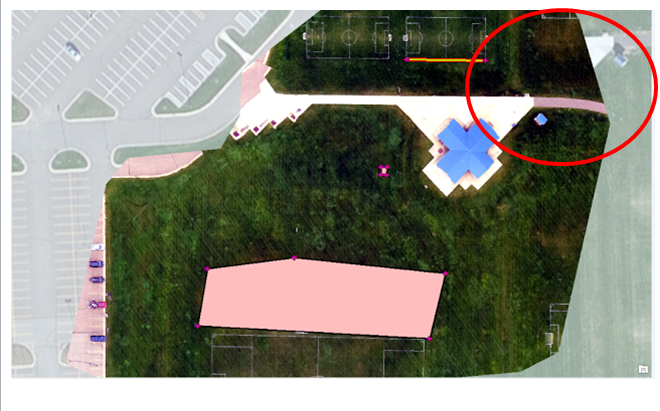 |
Discussion:
There were quite a few differences between the GEMs and the SX260. An example is above in Figure 27. If you notice on the image the mask is not lined up with the basemap, this distortion was measured and it was over 30 meters. As you see on the top of the image where the edge of the sidewalk does not match up, I have circled it in red so the difference is very noticeable. This shows the difference in the quality of the photo from the Pix4D compared to the photos with the Cannon SX260, the geolocation is not correct. So if you are needing an accurate image that is precise in the location, this is probably not your best bet. If you look at the map created, you will find many other areas that do not match up at all around the map, such as where the parking lot is on the far left of the image.
The quality report shows many different important aspects of the project. It tells the reader if the quality of the images is good, it shows which ones were used and updated. It shows the quality of the overlap. Below is another view of the overlap from the quality report above. This report shows how good the overlap is based on colors. The colors indicate the amount of images. As you see this is a really good overlap model. The bright green shows that there are 5 or more photos used for the overlap. The red areas show low overlap which you see there is very little red on this model.

Overall, the Pix4D was very easy to use, it gave clear instructions and it was easy to understand. Using the manual was the easiest one I have seen or used. I feel that I can understand the quality report too. I do believe that there could be more definitions to words and processes. I would have liked it if the site had more information on explaining what things were and not just how they worked. It does give a lot of information on GCP's which I found helpful. This program is really helpful and useful. It is also very accurate compared to the Canon SX260. I also think the trajectory of the map and the video of it was really new and different. I like how easy it was to make the waypoints exactly where I wanted them and make the video in a matter of minutes. This was even fun to use and to learn about. I would love to work with this program in the future. It is one of the best and most advanced programs out there and it was easy to use as well.
No comments:
Post a Comment